What Makes Self-Regulating Cables Different from Other Trace Heating Technologies
A frozen instrument line in a chemical plant. A burst water service pipe at a remote compressor station. A viscous fuel oil line that won't flow at winter startup. These failures share a common cause — inadequate or absent pipe heating — and a common solution that has dominated industrial heat tracing specification for over four decades.
Self-regulating cables occupy a specific and well-defined position among trace heating technologies. Unlike mineral-insulated cables, which must be manufactured to a fixed circuit length and operate at a fixed resistance, self-regulating cables can be cut to any length on site and automatically vary their heat output along every centimeter of their length. Unlike series-type constant wattage cables, they cannot overheat at overlap points, which simplifies installation significantly on valve clusters and instrument connections.
The tradeoff is temperature ceiling. Self-regulating cables are not the right choice for process lines requiring maintain temperatures above approximately 150°C, and they draw higher inrush current at cold startup than their nameplate wattage suggests. Understanding both capabilities and limits is what separates a well-specified installation from one that fails in the first cold season. For a full overview of industrial heat trace cables and trace heater systems, including the range of available cable types, the product category covers all primary technologies.
Cable Construction: Layers, Materials, and What Each Layer Does
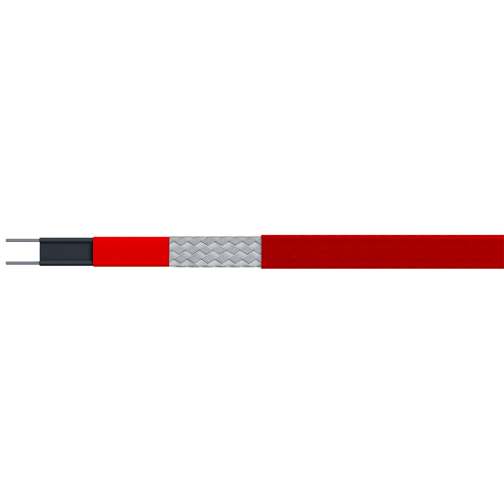
The self-regulating effect originates in a single component — the conductive polymer core — but the complete cable structure involves five or six distinct layers, each with a specific function. Understanding what each layer does explains both why the cable performs as it does and what can cause it to fail prematurely.
At the center sit two parallel copper bus wires, typically nickel-plated to resist oxidation at operating temperatures. These are not heating elements themselves; they are conductors that deliver voltage to the core along the full cable length. The conductive polymer core is extruded directly around and between these bus wires. This core — a precisely formulated blend of carbon black particles within a polyolefin or fluoropolymer matrix — is where electrical energy converts to heat. Its positive temperature coefficient (PTC) behavior means resistance rises as temperature rises, automatically reducing power output.
Over the core sits a dielectric insulation jacket, which provides electrical isolation between the live core and the outer layers. A metallic ground braid — typically tinned copper — surrounds the insulation jacket. This braid serves as the earth conductor required by electrical codes in most jurisdictions and provides mechanical protection against physical damage. The final outer jacket, in polyolefin or fluoropolymer depending on the application, protects against moisture ingress, UV exposure, and chemical attack. The cable's temperature rating and wattage designation are printed on this outer jacket for identification after installation.
For a deeper understanding of the PTC physics driving the self-regulation behavior and how cable grades are differentiated, the technical article on how self-regulating heat trace works and how to select the right grade covers the polymer science in detail.
Self-regulating cable layer construction and functions
| Layer |
Material |
Function |
| Bus wires |
Nickel-plated copper |
Deliver voltage along full cable length |
| Conductive polymer core |
Carbon-loaded polyolefin or fluoropolymer |
Generates heat; self-regulates via PTC response |
| Dielectric insulation jacket |
Polyolefin or fluoropolymer |
Electrical isolation between core and outer layers |
| Metallic ground braid |
Tinned copper |
Earth conductor; mechanical protection |
| Outer jacket |
Polyolefin (standard) or fluoropolymer (chemical/UV duty) |
Environmental protection; carries product identification |
Temperature Grades and Power Output: Choosing the Right Specification
Self-regulating cables are available in multiple temperature grades, defined by two key parameters: the maximum maintain temperature the cable can sustain, and the maximum intermittent exposure temperature the cable can withstand without permanent damage. Selecting the wrong grade — typically under-specifying to save cost — is one of the most common causes of premature cable degradation in industrial installations.
Low-temperature grades, generally rated to maintain temperatures up to around 65°C with maximum exposure temperatures near 85°C, cover the majority of freeze protection applications. Water service pipes, instrument impulse lines, drain lines, and domestic hot water circulation circuits all fall within this range. Medium-temperature grades, rated to maintain temperatures of 120–150°C with exposure ceilings near 200°C, serve light process heating duties — fuel oil lines, glycol systems, and moderately viscous chemical process streams. High-temperature self-regulating grades push maintain temperatures toward 150°C and beyond, though above this range, constant wattage or mineral-insulated cables generally provide better performance and longer service life.
Power output — rated in watts per meter at a reference temperature, typically 10°C — must match the calculated heat loss of the pipe being traced. Larger diameter pipes, poorly insulated runs, pipes in outdoor wind-exposed locations, and lines in particularly cold climates all require higher W/m outputs. Undersizing the output means the cable cannot maintain the target temperature in worst-case conditions; oversizing increases energy cost and, in some cases, can exceed the pipe material's temperature tolerance. For applications demanding elevated maintain temperatures, high-temperature trace heaters for freeze protection on elevated-temperature pipelines extend the performance envelope where standard self-regulating grades are insufficient.
Self-regulating cable grades by application and temperature range
| Grade |
Typical Maintain Temp |
Max Exposure Temp |
Typical Power Output |
Representative Applications |
| Low temperature |
Up to 65°C |
~85°C |
8–20 W/m |
Freeze protection, domestic water, instrument lines |
| Medium temperature |
65–120°C |
~200°C |
15–33 W/m |
Fuel oil, glycol lines, light process maintenance |
| High temperature |
120–150°C |
~250°C |
25–50 W/m |
Heavy process lines, steam condensate, viscous chemicals |
Industrial Applications: Where Self-Regulating Cables Are Specified
Self-regulating cables appear in almost every sector that operates pipework in cold climates or requires process temperature maintenance. The specific demands of each application determine which cable grade, jacket material, and control strategy is appropriate.
Pipe freeze protection is the single largest application globally. Water service lines, fire suppression systems, instrument impulse lines, and drain connections on outdoor or unheated structures all require trace heating wherever ambient temperatures can fall below 0°C. Self-regulating cables are the dominant technology here because the variable output means the cable automatically delivers more heat as ambient temperature drops, without requiring thermostat intervention at every point along the circuit.
In oil and gas facilities, self-regulating cables are used extensively on process instrument lines, analyzer sample lines, water injection lines, and produced water handling circuits. The ability to install safely in Zone 1 and Zone 2 hazardous areas — once properly certified — makes them practical for the majority of process pipework in these environments. Offshore platforms, where space is limited and corrosion resistance is critical, typically specify fluoropolymer-jacketed cables for their superior chemical and UV resistance.
In water and wastewater treatment, the combination of outdoor exposure, varying pipe diameters, and the need for reliable freeze protection over long runs makes self-regulating cable a consistently practical choice. The cut-to-length feature is particularly valuable on treatment plant pipe routes, which rarely follow straight runs. For standard temperature maintenance applications across process and utility systems, low-temperature trace heaters designed for standard temperature maintenance applications cover the majority of these use cases effectively.
Rooftop de-icing — gutters, downspouts, roof valleys, and eave edges — represents a significant commercial building application. Self-regulating cables here provide a distinct energy advantage: they draw maximum power only during active freezing conditions and reduce output automatically as the roof warms, which translates to substantially lower seasonal energy consumption compared to constant wattage alternatives.
Installation Best Practices for Self-Regulating Cables
Most self-regulating cable failures in service trace back to installation errors, not cable defects. The parallel circuit design makes these cables genuinely forgiving in many respects — but specific steps, done incorrectly, cause problems that appear months or years later.
Begin with an accurate heat loss calculation for each circuit before ordering cable. The required watts per meter at minimum ambient temperature, combined with the pipe insulation specification, determines the correct cable output rating. Once the cable is on site, measure each pipe run and cut the cable to length using sharp metal shears — not wire cutters, which can crush the bus wires. Self-regulating cables may be cut to any length without changing the circuit design, but the cut end must be properly sealed with a manufacturer-approved end cap before energization. An unsealed end allows moisture into the core, which degrades insulation resistance and eventually causes ground faults.
Attach the cable to the pipe using self-adhesive glass fiber tape, applied at 300mm intervals for straight runs. At valves, flanges, and pipe supports — which act as thermal bridges, drawing heat away from the pipe faster than surrounding sections — add extra cable loops to compensate for the additional heat loss. Self-regulating cables can safely overlap at these points without risk of burnout, which is one of their most significant practical installation advantages over series-resistance types.
Apply thermal insulation over the cable and pipe after all connections are tested. The insulation thickness specified in the heat loss calculation is a minimum, not a guideline — undersized insulation forces the cable to work harder than designed and may mean target temperatures cannot be reached in extreme weather. Before closing out the installation, perform a megohm insulation resistance test between the bus wires and the ground braid. A reading above 20 MΩ is generally acceptable for a new installation; significantly lower readings indicate a wiring fault, a damaged end seal, or moisture contamination that must be resolved before energizing the circuit.
Hazardous Area Certification: What ATEX, IECEx, and IEEE 515 Require
Specifying self-regulating cables for use in classified hazardous areas — where flammable gases, vapors, or combustible dusts may be present — requires more than selecting a cable with the right wattage and temperature grade. The cable and its complete system must carry recognized third-party certification, and the installation must comply with the applicable area classification standard.
In Europe and many international markets, ATEX certification (under the EU ATEX Directive) is the baseline requirement for equipment used in explosive atmospheres. IECEx certification, issued under the IEC international system, is accepted in a growing number of countries as an equivalent alternative and is increasingly specified on international projects. Both frameworks require that the cable be tested to confirm its maximum surface temperature — the T-Code — under worst-case conditions: maximum ambient temperature, maximum circuit length, and where applicable, cable overlapped on itself.
The T-Code must be lower than the auto-ignition temperature of the hazardous substance present in the installation area. This is the core safety logic: a cable that cannot reach ignition temperature cannot ignite an explosive atmosphere, even under fault conditions. This is where the self-regulating cable's inherent output-limiting behavior provides a genuine safety margin over fixed-output alternatives, which require external thermal cutouts to achieve the same protection.
In North America, IEEE 515-2017, the standard for testing, design, installation, and maintenance of electrical resistance trace heating for industrial applications, sets the technical framework for heat trace design and qualification. It covers both ordinary and classified locations, prescribes testing methods for cable qualification, and provides the basis for electrical and thermal design calculations that engineers must follow to achieve compliant installations.
Maintenance and Fault Diagnosis
A well-installed self-regulating cable system requires relatively little ongoing maintenance, but it is not maintenance-free. The insulation resistance of every circuit should be tested annually before the heating season, using a 500V or 1000V insulation resistance meter between the bus wires and the ground braid. A steady decline in IR readings over successive annual tests — even if still above minimum thresholds — is an early indicator of moisture ingress or jacket degradation that should be investigated before failure occurs.
The most useful diagnostic tool for a fully installed system is an infrared thermal camera. With the system energized under cold conditions, scanning the pipe run will reveal cold spots — sections where the cable is not delivering heat — which typically indicate a failed end seal, a broken bus wire connection, or a section of cable that has been mechanically damaged and lost electrical continuity. Infrared scanning is non-invasive and can locate faults on long pipe runs in minutes, without disturbing the thermal insulation.
Common fault patterns and their causes follow predictable patterns. Persistent low insulation resistance usually points to a compromised end seal or a damaged outer jacket allowing moisture into the cable. Nuisance circuit breaker tripping on cold morning startups is almost always caused by inrush current exceeding the breaker rating — the solution is a correctly sized breaker with a time-delay characteristic matched to the cable's cold startup inrush profile, not replacing the cable. A circuit that simply fails to maintain temperature in cold weather, despite passing electrical tests, typically indicates insulation that has degraded, settled, or been damaged during maintenance work, reducing its thermal resistance below the design assumption.
 English
 русский
 Français
 Español
 عربى
عربى